ExROM: Difference between revisions
From NESdev Wiki
Jump to navigationJump to search
(→Solder Pad Config: CL3/SL3 don't appear to be related to fine vertical scrolling - they control pins 97 and 98) |
mNo edit summary |
||
| Line 17: | Line 17: | ||
== Solder Pad Config == | == Solder Pad Config == | ||
* MMC5 in 'CL mode' (default) : 'CL4', 'CL5', and 'CL6' connected; | * MMC5 in 'CL mode' (default) : 'CL4', 'CL5', and 'CL6' connected; 'SL4', 'SL5', and 'SL6' disconnected. | ||
* MMC5 in 'SL mode' : 'CL4', 'CL5', and 'CL6' disconnected; | * MMC5 in 'SL mode' : 'CL4', 'CL5', and 'CL6' disconnected; 'SL4', 'SL5', and 'SL6' connected. | ||
Unlike [[SxROM|SOROM]], which battery-backs the second RAM, ETROM battery-backs the ''first'' RAM. | Unlike [[SxROM|SOROM]], which battery-backs the second RAM, ETROM battery-backs the ''first'' RAM. | ||
Latest revision as of 17:00, 4 February 2022
The generic designation ExROM refers to cartridge boards made by Nintendo that use the Nintendo MMC5 mapper.
Board Types
The following ExROM boards are known to exist:
| Board | PRG ROM | PRG RAM | CHR |
|---|---|---|---|
| EKROM | 128 / 256 / 512 / 1024 KB | 8 KB | 128 / 256 / 512 / 1024 KB ROM |
| ELROM | 128 / 256 / 512 / 1024 KB | 128 / 256 / 512 / 1024 KB ROM | |
| ETROM | 128 / 256 / 512 / 1024 KB | 16 KB (2x 8KB) | 128 / 256 / 512 / 1024 KB ROM |
| EWROM | 128 / 256 / 512 / 1024 KB | 32 KB | 128 / 256 / 512 / 1024 KB ROM |
Solder Pad Config
- MMC5 in 'CL mode' (default) : 'CL4', 'CL5', and 'CL6' connected; 'SL4', 'SL5', and 'SL6' disconnected.
- MMC5 in 'SL mode' : 'CL4', 'CL5', and 'CL6' disconnected; 'SL4', 'SL5', and 'SL6' connected.
Unlike SOROM, which battery-backs the second RAM, ETROM battery-backs the first RAM.
- RAM chip with data retention (default) : 'CL2' connected, 'SL2' disconnected, with Battery, D1, R5, R6, and R8 present.
- RAM chip without data retention : 'CL2' disconnected, 'SL2' connected, with Battery, D1, R5, and R6 removed.
- Second RAM chip (if present) with data retention : 'CL1' disconnected, with battery, D1, R7, and R8 present.
- Second RAM chip (if present) without data retention (default) : 'CL1' connected, 'SL1' disconnected, R7 removed.
- NES-ETROM can be trivially modified to support 2×32 KiB RAMs without needing rewiring, using the CL15 and SL15 solder jumpers. 'CL15' by default connects SRAM pin 26 (PRG RAM +CE on an 8 KiB RAM) to MMC5 pin 83 (PRG RAM +CE). 'SL15' instead connects the same pin 26 (PRG RAM A13 on a 32 KiB RAM) to MMC5 pin 69 (PRG RAM A13). PRG RAM pin 1 (no connection / PRG RAM A14) is always connected to the MMC5.
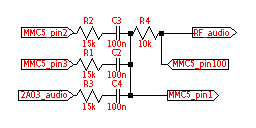
- Sound circuitry used (Famicom): R1, R2, R3, R4, C2, C3, and C4 present (HVC-ExROM). No Famicom cartridges ever disabled the MMC5 audio as the traces on the circuit board do not permit the MMC5's amplifier to be bypassed.
- Sound circuitry used (NES) : R1, R2, R4, R9, C2, C3 present (NES-ExROM). An American or European NES must be modified to output cartridge audio, even if the audio circuitry is implemented.
- Sound circuitry unused : R1, R2, R4, R9, C2, and C3 not present (NES-ExROM).
NES-ExROM boards entirely omitted R3 and C4, and added R9 (nominally 10kΩ) between R4 and the output to the cartridge edge. The silkscreened values on NES-EKROM and NES-EWROM, and Famicom games that actually used the expansion audio, replace R1 with 6.8kΩ. This increases the volume of the pulse waves by 6.9dB, and is believed to equalize the volume of the MMC5 pulse waves to the internal ones. MMC5 pins 1 and 100 are some kind of inverter used as an amplifier.
