ExROM
From NESdev Wiki
Jump to navigationJump to search
The generic designation ExROM refers to cartridge boards made by Nintendo that use the Nintendo MMC5 mapper.
Board Types
The following ExROM boards are known to exist:
| Board | PRG ROM | PRG RAM | CHR |
|---|---|---|---|
| EKROM | 128 / 256 / 512 / 1024 KB | 8 KB | 128 / 256 / 512 / 1024 KB ROM |
| ELROM | 128 / 256 / 512 / 1024 KB | 128 / 256 / 512 / 1024 KB ROM | |
| ETROM | 128 / 256 / 512 / 1024 KB | 16 KB (2x 8KB) | 128 / 256 / 512 / 1024 KB ROM |
| EWROM | 128 / 256 / 512 / 1024 KB | 32 KB | 128 / 256 / 512 / 1024 KB ROM |
Solder Pad Config
- MMC5 in 'CL mode' (default) : 'CL3', 'CL4', 'CL5' and 'CL6' connected, 'SL3', 'SL4', 'SL5' and 'SL6' disconnected.
- MMC5 in 'SL mode' : 'CL3', 'CL4', 'CL5' and 'CL6' disconnected, 'SL3', 'SL4', 'SL5' and 'SL6' connected.
- RAM chip with data retention (default) : 'CL2' connected, 'SL2' disconnected, with Battery, D1, R5, R6, R8 present.
- RAM chip without data retention : 'CL2' disconnected, 'SL2' connected, with Battery, D1, R5 and R6 removed.
- Second RAM chip (if present) with data retention : 'CL1' disconnected, with battery, D1 and R7, R8 present.
- Second RAM chip (if present) without data retention (default) : 'CL1' connected, 'SL1' disconnected, R7 removed.
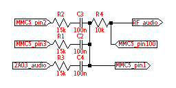
- Sound circuitry used (Famicom): R1, R2, R3, R4, C2, C3, and C4 present (HVC-ExROM). No Famicom cartridges ever disabled the MMC5 audio as the MMC5's amplifier is integral.
- Sound circuitry used (NES) : R1, R2, R4, R9, C2, C3 present (NES-ExROM). An American or European NES must be modified to output cartridge audio, even if the audio circuitry is implemented.
- Sound circuitry unused : R1, R2, R4, R9, C2, and C3 not present (NES-ExROM).
NES-ExROM boards entirely omitted R3 and C4, and added R9 (nominally 10kΩ) between R4 and the output to the cartridge edge. The silkscreened values on NES-EKROM and NES-EWROM, and Famicom games that actually used the expansion audio, replace R1 with 6.8kΩ. This increases the volume of the pulse waves by 6.9dB, and is believed to equalize the volume of the MMC5 pulse waves to the internal ones. MMC5 pins 1 and 100 are probably an inverter used as an amplifier.
- NES-ETROM additionally provides a solder jumper pair 'CL15' and 'SL15'. It is not known what this does.
