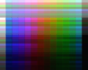
Full palette demo
This demo shows the normal 56-color NES palette using all eight color tint settings, for a total of over 400 colors on screen at once. It does this using the PPU's direct color control mode and cycle-timed code to make a nice grid. It also uses a table of palette/tint values, making it easy to change the color pattern. Traditional and smoother arrangements are provided.
The archive contains ROMs for both palette arrangements, along with well-organized and commented ca65-compatible assembly source code. It has been tested on an NTSC front-loader NES.
A few special PPU techniques are used in this demo, described below.
Direct color control
Normally, the PPU displays the palette byte from $3F00 as the background color. When rendering is disabled and the PPU address is in the $3F00-$3FFF range, the PPU displays the palette byte at that address. By changing the address and bytes in the palette at the proper times during each scanline, primitive images can be drawn. The upper bits of $2001 affect color tint, and can further be used to affect the color of images drawn using this technique. Each CPU clock corresponds to three pixels.
The simplest method to draw an image is to set up a palette in advance, then manipulate the PPU address during a scanline. This allows 28 total colors ($3F00-$3F1F, minus four mirrored entries). It's limited in horizontal resolution since changing the PPU address to an arbitrary new palette entry takes at least eight CPU clocks (two $2006 writes).
A more flexible method is to write to the palette during each scanline. This can be done in less time, and puts no limitation on the number of colors. One snag is that after writing to $2007, the PPU address is incremented to the next palette entry, so the color just written won't be displayed until we set the PPU address to the previous entry again (actually, the color will be displayed immediately, but only for around one pixel). Since we can't write more than around 20 bytes to $2007 each scanline, we can just write the next scanline's colors each time. Then come the next scanline, those colors will be in the palette and displayed as we write more colors.
Reducing horizontal image shaking
The PPU has two frame lengths, short and long, and an internal flag that toggles every frame and determines whether the frame will be short or long. A long frame is 341*262 PPU clocks, while a short is one PPU clock less. The optional clock occurs around the end of VBL. If rendering is disabled, the frame is long regardless of the flag.
For the direct color technique, we want rendering off. If we simply leave rendering off all the time, every frame will be 341*262=89342 PPU clocks. This is 29780 2/3 CPU clocks, so the pixels we draw can't be horizontally stable. We can only delay a whole number of CPU clocks. So we delay 29781 clocks after the beginning of the first frame, which is 1/3 too much. This puts the second frame's image one pixel to the right. The same occurs for the third frame, leaving the image shifted another pixel. Now, we can delay one clock less for the fourth frame, shifting the image back to where it was on the first frame.
If instead we have rendering enabled during that time near the end of VBL where the skipped PPU clock occurs every other frame, but then disabled when doing our drawing, we can have the image shake by only one pixel. This is because the fractional CPU cycles from a pair of short and long frames totals a whole CPU cycle.
There is one more snag with avoiding shaking. A pair of short and long frames totals 29780 2/3 + 29780 1/3 = 59561 CPU clocks, so we need to delay 29780.5 CPU clocks each frame. To handle that half clock, we must delay an extra clock every other frame. When we do so, our image will shift to the right by three pixels. We want this three-pixel shift synchronized with a short frame, not a long frame, otherwise the image will shake by two pixels.
Synchronizing precisely to PPU
To reduce shaking and put the image in a consistent position, we must synchronize exactly to the beginning of the PPU's VBL and a long frame.
To synchronize exactly to the beginning of VBL, we first disable rendering. This makes all frames long, 29780 2/3 CPU clocks long. Then we run a delay loop that reads $2002 every 29781 CPU clocks. Since the VBL period is 1/3 CPU clock less, the time of VBL relative to this $2002 read will be 1/3 CPU clock earlier each time. The loop starts out reading $2002 a few clocks before VBL begins. Each iteration it inches closer and closer, until it reads $2002 when the VBL flag is set. The CPU is now synchronized to VBL to an accuracy of 1/3 CPU clock.
Then, we must determine whether the PPU is currently on an even or odd frame. We first delay one frame with rendering still off. This will shift the VBL 1/3 a CPU clock earlier. Then we enable rendering for a frame, and read $2002. If this was a short frame, the VBL will have shifted earlier by 2/3 CPU clock, totaling with the 1/3 to one CPU clock. This will cause the $2002 read to find the VBL flag set. We're done if this is the case. If not, we disable rendering and delay another frame. This will shift the VBL time earlier by 1/3 CPU clock, now also totaling a whole CPU clock (three thirds), so we're at the same synchronization as the short case. And even though rendering is disabled, this will toggle the short/long flag inside the PPU, so that it also matches the other case. We're now exactly synchronized in both respects.

